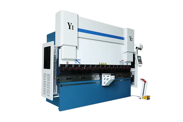

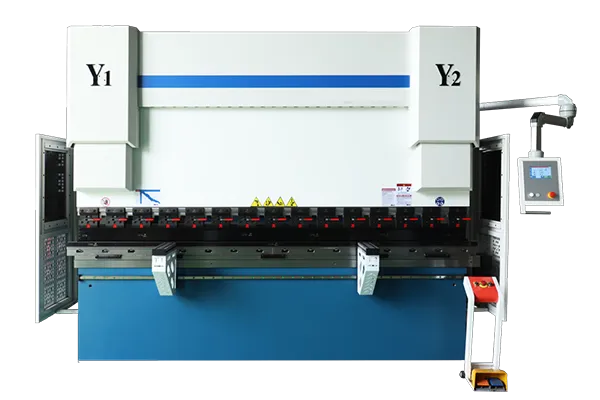
LONGBOW Precision CNC press brake
Precision CNC press brake For The More Demanding Taste
Superior Quality. Reliability In An Economical Machine
The Maanshan Changgong CNC Press Brake is a standout in the world of precision machining. Known for its exceptional accuracy and affordability, this machine brings high-end capabilities within reach for a wide range of industries. Designed to deliver precise bending and forming of sheet metal, it combines advanced CNC technology with robust construction, ensuring consistent performance and durability.
Despite its cost-effective price point, the Maanshan Changgong CNC Press Brake does not compromise on quality. It features state-of-the-art components and user-friendly controls, making it an ideal choice for both small workshops and large manufacturing facilities. Whether you’re looking to streamline your production process or achieve intricate bends with minimal effort, this press brake offers unmatched value and efficiency.
Choose the Maanshan Changgong CNC Press Brake for a reliable, precise, and budget-friendly solution to your metal forming needs.
Includes Following Features And Properties
Clamping System:
CNC System:
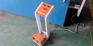
Control System:
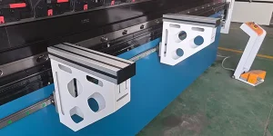
Sheet Follower :
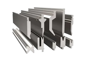
Press Brake Tool :
Less Waste, Less Maintenance Costs
High Performances
Same Job, 50% Less Energy
<High Dynamic Y-axis Control
Standard Equipment
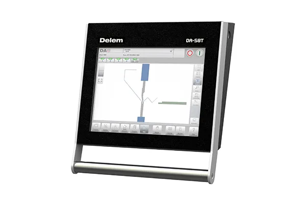
- CNC DELEM DA53T with 2D colour graphics
- LONGBOW® BGA-2 for X=500mm X,R-Axis
- Tool kit: 4 V die (V=16-22-35-50) series of 835mm punches
- LONGBOW Pro Manual wave crowning system
- GIVI optical scales
- Lazer Safe dual beam photocells
- Hoerbiger (HAWEI) hydraulic system
- High efficiency motor – class IE3
- Electrical cabinet with Schneider, Siemens components
Technical Specifications
| Model | Bending Force | Bending Length(A) | Oil Tank | Approaching Speed | Ram Speed | Return Speed | X – axis Stroke | X – axis Speed | Raxis Stroke | Raxis Speed | Column Distance (B) | Throat Depth (D) | Stroke (C) | Daylight (E) | Step/Servo Motor | Weight | Dimensions |
| Unit | KN | mm | L | mm/s | mm/s | mm | mm/s | mm | mm | mm/s | mm | mm | mm | mm | KW | Ton | L×W×H mm |
| 50T/1300 | 500 | 1300 | 170 | 160 | 13 | 160 | 500 | 350 | 200 | 200 | 1120 | 250 | 150 | 460 | 5.5/6 | 4 | 1800*1500*2300 |
| 50T/2000 | 500 | 2000 | 170 | 160 | 13 | 160 | 500 | 350 | 200 | 200 | 1600 | 250 | 150 | 460 | 5.5/6 | 4.3 | 2600*1500*2300 |
| 70T/1600 | 700 | 1600 | 170 | 220 | 13 | 160 | 500 | 350 | 200 | 200 | 1300 | 300 | 150 | 460 | 5.5/6 | 5.1 | 1800*1600*2500 |
| 70T/2500 | 700 | 2500 | 170 | 220 | 13 | 160 | 500 | 350 | 200 | 200 | 2050 | 300 | 150 | 460 | 5.5/6 | 5.6 | 3100*1600*2500 |
| 70T/3200 | 700 | 3200 | 170 | 220 | 13 | 160 | 500 | 350 | 200 | 200 | 2700 | 300 | 150 | 460 | 5.5/6 | 6.6 | 3700*1600*2500 |
| 80T/2500 | 800 | 2500 | 170 | 220 | 12 | 145 | 500 | 350 | 200 | 200 | 2050 | 300 | 150 | 460 | 7.5/7.8 | 6 | 3100*1600*2600 |
| 110T/2500 | 1100 | 2500 | 170 | 220 | 12 | 160 | 500 | 350 | 200 | 200 | 2050 | 400 | 200 | 480 | 11/10.8 | 7 | 3100*1800*2600 |
| 110T/3200 | 1100 | 3200 | 170 | 220 | 12 | 160 | 500 | 350 | 200 | 200 | 2700 | 400 | 200 | 480 | 11/10.8 | 7.6 | 3800*1800*2600 |
| 110T/4000 | 1100 | 4000 | 170 | 220 | 12 | 160 | 500 | 350 | 200 | 200 | 3100 | 400 | 200 | 480 | 11/10.8 | 8.8 | 4600*1800*2600 |
| Model | Bending Force | Bending Length(A) | Oil Tank | Aprroaching Speed | Ram Speed | Return Speed | X-axis stroke | X-axis Speed | R-axis stroke | R-axis Speed | Column Distance(B) | Throat Depth(D) | Stroke(C) | Daylight(E) | Step/Servo Motor | Weight | Dimensions |
| 110T/4100 | 1100 | 4100 | 170 | 220 | 12 | 160 | 500 | 350 | 200 | 20c | 3600 | 400 | 200 | 480 | 11/10.8 | 9 | 4700*1800*2700 |
| 135T/3200 | 1350 | 3200 | 170 | 220 | 10 | 130 | 500 | 350 | 200 | 200 | 2700 | 400 | 200 | 480 | 11/10.8 | 9 | 3800*1800*2700 |
| 135T/4000 | 1350 | 4003 | 170 | 220 | 10 | 130 | 500 | 350 | 200 | 200 | 3100 | 400 | 200 | 480 | 11/10.8 | 9.4 | 4600*1800*2700 |
| 135T/4100 | 1350 | 4100 | 170 | 220 | 10 | 130 | 500 | 350 | 200 | 200 | 3600 | 400 | 200 | 480 | 11/10.8 | 9.6 | 4700*1800*2700 |
| 1707/2500 | 1700 | 2500 | 300 | 160 | 10 | 100 | 500 | 350 | 200 | 200 | 2050 | 450 | 200 | 480 | 15/13.2 | 10.4 | 3100*2000*2800 |
| 1/01/3200 | 1/00 | 3200 | 300 | 160 | 10 | 100 | 500 | 350 | 200 | 200 | 2/00 | 450 | 200 | 480 | 15/13.2 | 11.3 | 3800*2000*2800 |
| 170T/4000 | 1700 | 4000 | 300 | 160 | 10 | 100 | 500 | 350 | 200 | 200 | 3100 | 450 | 200 | 480 | 15/13.2 | 12.3 | 4600*2000*2800 |
| 170T/4100 | 1700 | 4101 | 300 | 160 | 10 | 100 | 500 | 350 | 200 | 200 | 3600 | 450 | 200 | 400 | 15/13.2 | 12.5 | 4700*2000*2800 |
| 220T/2500 | 2200 | 2500 | 300 | 160 | 9 | 105 | 500 | 350 | 200 | 200 | 2050 | 450 | 200 | 480 | 18.5/16.7 | 12 | 3100*2200*2850 |
| 220T/3200 | 2200 | 3200 | 300 | 160 | 9 | 105 | 500 | 350 | 200 | 200 | 2600 | 450 | 200 | 480 | 18.5/16.7 | 12.8 | 3800*2200*2850 |
| Model | Bending Force | Bending Length(A) | Oil Tank | Aprroaching Speed | Ram Speed | Return Speed | X-axis stroke | X-axis Speed | R-axis stroke | R-axis Speed | Column Distance(B) | Throat Depth(D) | Stroke(C) | Daylight(E) | Step/Servo Motor | Weight | Dimensions |
| 220T/4000 | 2200 | 4000 | 300 | 160 | 9 | 105 | 500 | 350 | 200 | 200 | 3100 | 450 | 200 | 480 | 16.5/16.7 | 14 | 4600*2200*2850 |
| 220T/5000 | 2200 | 5000 | 300 | 160 | 9 | 105 | 500 | 350 | 200 | 200 | 4000 | 450 | 200 | 480 | 18.5/16.7 | 19 | 4600*2200*2850 |
| 250T/2500 | 2500 | 2500 | 460 | 100 | 8.5 | 100 | 500 | 350 | 200 | 200 | 2000 | 450 | 250 | 540 | 22/16.7 | 15.5 | 3100*2000*2900 |
| 250T73200 | 2500 | 3200 | 460 | 100 | 8.5 | 100 | 500 | 350 | 200 | 200 | 2600 | 450 | 250 | 540 | 22/16.7 | 16.1 | 3500*2000*2900 |
| 250T/4000 | 2500 | 4000 | 460 | 100 | 8.5 | 100 | 500 | 350 | 200 | 200 | 3100 | 450 | 250 | 540 | 22/16.7 | 17.8 | 4300*2100*3100 |
| 250T/5000 | 2500 | 5000 | 460 | 100 | 8.5 | 100 | 500 | 350 | 200 | 200 | 3300 | 450 | 250 | 540 | 22/16.7 | 23.3 | 5300*2150*3150 |
| 250T/6000 | 2500 | 6000 | 460 | 100 | 8.5 | 100 | 500 | 350 | 200 | 200 | 4800 | 450 | 250 | 540 | 22/16.7 | 25 | 6300*2150*3150 |
| 330T/3200 | 3000 | 3200 | 650 | 80 | 8.5 | 110 | 500 | 350 | 200 | 200 | 2600 | 500 | 250 | 570 | 22 | 18.8 | 3500*2250*3200 |
| 300T/4000 | 3000 | 4000 | 650 | 80 | 8.5 | 110 | 500 | 350 | 200 | 200 | 3100 | 500 | 250 | 570 | 22 | 20.3 | 4300*2500*3400 |
| 300T/5000 | 3000 | 5000 | 650 | 80 | 8.5 | 110 | 500 | 350 | 200 | 200 | 3800 | 500 | 250 | 570 | 22 | 27 | 5300*2500*3400 |
| Model | Bending Force | Bending Length(A) | Oil Tank | Aprroaching Speed | Ram Speed | Return Speed | X-axis stroke | X-axis Speed | R-axis stroke | R-axis Speed | Column Distance(B) | Throat Depth(D) | Stroke(C) | Daylight(E) | Step/Servo Motor | Weight | Dimensions |
| 300T/6000 | 3000 | 6000 | 650 | 80 | 8.5 | 110 | 500 | 350 | 200 | 200 | 4800 | 500 | 250 | 570 | 22 | 30.4 | 6300*2500*3400 |
| 400T/3200 | 4000 | 3200 | 760 | 80 | 8 | 80 | 980 | 220 | 200 | 40 | 2400 | 500 | 300 | 610 | 30 | 22.8 | 3500*2700*3500 |
| 400T/4000 | 4000 | 4000 | 760 | 80 | 8 | 80 | 980 | 200 | 200 | 40 | 3100 | 500 | 300 | 610 | 30 | 28.3 | 4300*2700*3500 |
| 400T/5000 | 4000 | 5000 | 760 | 80 | 8 | 80 | 980 | 200 | 200 | 40 | 3800 | 500 | 300 | 610 | 30 | 31.2 | 5300*2700*3500 |
| 400T/6000 | 4000 | 6000 | 760 | 80 | 8 | 80 | 980 | 200 | 200 | 40 | 4800 | 500 | 300 | 610 | 30 | 37.4 | 6300*2700*3500 |
| 400T/8000 | 4000 | 6000 | 760 | 80 | 8 | 80 | 980 | 200 | 200 | 40 | 6400 | 500 | 300 | 610 | 30 | 52.8 | 630N*2700*3500 |
| 500T/4000 | 5000 | 4000 | 760 | 80 | 8.5 | 90 | 980 | 220 | 200 | 40 | 3100 | 500 | 300 | 610 | 37 | 35 | 4300*2700*3500 |
| 500T/5000 | 5000 | 5000 | 760 | 80 | 8.5 | 90 | 980 | 200 | 200 | 40 | 3800 | 500 | 300 | 610 | 37 | 39.8 | 5300*2700*3500 |
| 500T/6000 | 5000 | 6000 | 760 | 80 | 8.5 | 90 | 980 | 200 | 200 | 40 | 4000 | 500 | 300 | 610 | 37 | 45.8 | 6300*2700*3600 |
| 600T/3200 | 6000 | 3200 | 1050 | 80 | 8.5 | 85 | 980 | 200 | 200 | 40 | 2300 | 600 | 320 | 650 | 45 | 45 | 4300*3300*3900 |
| Model | Bending Force | Bending Length(A) | Oil Tank | Aprroaching Speed | Ram Speed | Return Speed | X-axis stroke | X-axis Speed | R-axis stroke | R-axis Speed | Column Distance(B) | Throat Depth(D) | Stroke(C) | Daylight(E) | Step/Servo Motor | Weight | Dimensions |
| 600T/4000 | 6000 | 4000 | 1050 | 80 | 8.5 | 85 | 980 | 200 | 200 | 40 | 3100 | 600 | 320 | 650 | 45 | 45.8 | 4330-3300*3900 |
| 603T/3000 | 6000 | 5000 | 1050 | 80 | 8.5 | 85 | 980 | 220 | 200 | 40 | 3800 | 600 | 320 | 650 | 45 | 50.3 | 5300*3300*3900 |
| 600T/6000 | 6000 | 6000 | 1050 | 80 | 8.5 | 85 | 980 | 200 | 200 | 40 | 4800 | 600 | 320 | 650 | 45 | 56.8 | 6300*3300*3900 |
| 600T/7000 | 5000 | 7000 | 1050 | 80 | 8.5 | 85 | 980 | 200 | 200 | 40 | 5000 | 600 | 320 | 650 | 45 | 66.8 | 7300*3300*3900 |
| 700T/6000 | 7000 | 6000 | 1050 | 80 | 8.5 | 85 | 980 | 200 | 200 | 40 | 4900 | 600 | 320 | 700 | 55 | 66.8 | 6300*3500*4000 |
| 800T/6000 | 8000 | 6000 | 1800 | 80 | 8 | 90 | 980 | 220 | 200 | 40 | 4600 | 600 | 320 | 800 | 30*2 | 76.8 | 6300*3500*4000 |
| 800T/7000 | 8000 | 7000 | 1800 | 80 | 8 | 90 | 980 | 200 | 200 | 40 | 5600 | 600 | 320 | 800 | 30*2 | 7300*3500*4200 | |
| 800T/8000 | 8000 | 8000 | 1000 | 80 | 8 | 90 | 980 | 200 | 200 | 40 | 6600 | 600 | 320 | 800 | 30*2 | 8300*3600*4500 | |
| 800T/10000 | 8000 | 10000 | 1800 | 80 | 8 | 90 | 980 | 200 | 200 | 40 | 7800 | 600 | 320 | 800 | 30*2 | 10300*3600*4900 |
Core Features of Precision CNC press brake
Bending machine bed
The bed is the basic support structure of the press brake, which needs to withstand various forces and moments generated by the press brake during the working process. Therefore, the structure and material of the bed have a great impact on the performance and accuracy of the press brake.
The bed of the electro-hydraulic servo press brake usually adopts an integral welded structure, which has high stiffness and high stability. The steel plate of the bed is welded with high quality steel plate, and has high precision and stability after strict annealing and stress relief treatment.
Hydraulic system
The hydraulic station is the core of the hydraulic system, which controls the movement of the machine by controlling the pressure and flow of the liquid. The main motor consists of a servo motor tank made of stainless steel. A hydraulic station usually consists of the following main components:
Hydraulic pump: Hydraulic pump is the power component of the hydraulic system, which converts mechanical energy into hydraulic energy and provides power for the entire hydraulic system.
Crowning
Our independently designed system calculates the compensation value based on the overall deformation of both the ram and worktable. This enables the deformation curve of the bed to align seamlessly with the compensation curve, ensuring optimal straightness and angle consistency in our products.
Manual Upper Tool Clamping
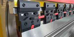
The one-key release fast clamp could ensure the safe and fast punch changing, with strict quality requirements and procurement standards of raw materials, which keeps the punch from falling out.
Ball Screw & Guide
The machine features ball screws and linear guide rails to ensure smooth and reliable operation.
Servo motor
The machine features ball screws and linear guide rails to ensure smooth and reliable operation.
Bending machine bed
The bed is the basic support structure of the press brake, which needs to withstand various forces and moments generated by the press brake during the working process. Therefore, the structure and material of the bed have a great impact on the performance and accuracy of the press brake.
The bed of the electro-hydraulic servo press brake usually adopts an integral welded structure, which has high stiffness and high stability. The steel plate of the bed is welded with high quality steel plate, and has high precision and stability after strict annealing and stress relief treatment.
Hydraulic System
The hydraulic station is the core of the hydraulic system, which controls the movement of the machine by controlling the pressure and flow of the liquid. The main motor consists of a servo motor tank made of stainless steel. A hydraulic station usually consists of the following main components:
Hydraulic pump: Hydraulic pump is the power component of the hydraulic system, which converts mechanical energy into hydraulic energy and provides power for the entire hydraulic system.
Crowning
Our independently designed system calculates the compensation value based on the overall deformation of both the ram and worktable. This enables the deformation curve of the bed to align seamlessly with the compensation curve, ensuring optimal straightness and angle consistency in our products.
Manual Upper Tool Clamping
The one-key release fast clamp could ensure the safe and fast punch changing, with strict quality requirements and procurement standards of raw materials, which keeps the punch from falling out.
Ball Screw & Guide
The machine features ball screws and linear guide rails to ensure smooth and reliable operation.
Servo motor
The machine features ball screws and linear guide rails to ensure smooth and reliable operation.
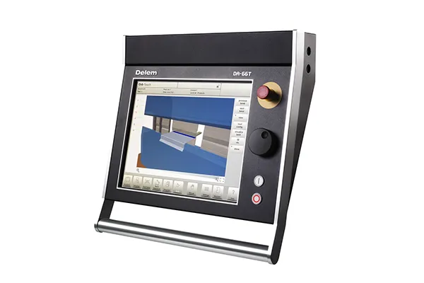
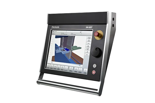
CNC Control System
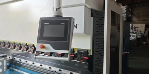
The new generation press brake controls offer an even higher grade of efficiency in programming, operation and control of today’s press brakes.
Press Brake Tool Selection
The right combination of punch and die is essential for achieving the desired bending shape. We offer a wide range of tooling options tailored to meet the diverse bending requirements of our customers.
1-V R Type General Upper Die Bending
1-V Offset Upper Die Bending
2-V 30° Acute Angle Upper Die Bending
2-V 85° Gooseneck Upper Die Bending
2-V 85° General Upper Die Bending
2-V 85° Straight Sword Upper Die Bending
2-V 85° Specialized Upper Die Bending
Pneumatic Double-Sided Folding and Bending
Optional Configurations
Hydraulic Clamping System
Laser Protection
Sheet Follower
Contact Us
Not sure which machine is right for your sheet metal product? Let our knowledgeable sales team guide you in selecting the most suitable solution for your needs.